The “niotix IEC-60870-5-104” module is an extension for niotix for integrating measurement data from niotix into network control systems via the telecontrol protocol IEC-60870-5-104. The module consists of the components “Connector IEC-60870-5-104 Push” in niotix and the separate component “niotix IEC-104 Server”. The niotix IEC-60870-5-104 module offers a robust solution for the seamless integration of IoT data into network control systems or other telecontrol systems.
Key features of the solution are:
- Automated configuration of the niotix IEC-104 server data points: the data points are automatically taken from niotix and do not need to be configured separately in the IEC-104 server.
- Automated configuration of the IEC-104 server: Several IEC-104 servers can be started automatically depending on the configuration of the connectors in niotix.
- Operation on virtual server infrastructure: The niotix IEC-104 server component is delivered as a Docker container and can therefore be operated scalably and reliably on virtual infrastructure. Delivery on dedicated hardware is also possible.
- Data points can be automatically provided with IEC quality flags.
- Data points can be configured in niotix via an API, allowing large volumes of data points to be processed efficiently.
- Event-based communication between niotix and the niotix IEC 104 server - the data points are transferred when they are updated, which means that fast changes are also transferred to the control system.
- Can be used with digital twins and virtual devices: this also allows aggregated values and IoT data from any source to be sent to the control system
General information
Measurement data is integrated into the grid control system via the IEC-60870-5-104 push connector within niotix and the niotix IEC-104 server with connection to the control system.
The following diagram shows the components of the module and the basic data flow:
niotix IEC-60870-5-104 push connector
The IEC-60870-5-104 push connector is an outgoing connector in niotix, which sends data to the niotix IEC-104 server with an integration flow. In addition to the standard metadata, the outbound packets also contain the outbound_values object, which contains the IEC-104-specific parameters.
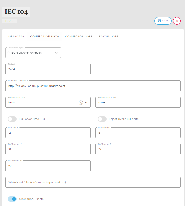
Configuration options of the connector
The IEC-104 push connector in niotix enables user-friendly configuration for the transmission of data points. The following settings can be made:
- Instance name: Give the connector an individual, easy-to-understand name.
- Description: Enter a short description.
- IEC Port: Enter the desired port of the niotix IEC-104 server for communication with the control system. The default port is 2404.
- IEC Server Push URL: Enter the URL of the IEC server for data reception here.
- Header Auth Type: Enter the type of authentication
- Header Auth Value: Enter the value of the authentication
- IEC Server Time UTC: Activate this toggle button to set the server time to UTC.
- Reject invalid SSL certs: Activate this toggle button to reject invalid SSL certificates.
- IEC k Value: Specify the maximum number of unconfirmed Application Protocol Data Units (APDU) that the IEC104 server should send via this channel before waiting for confirmation from the control system that these APDUs have been successfully received. (Value: 1 - 32767)
- IEC w Value: Specify the maximum number of APDUs that the IEC-104 server can receive on this channel before it sends an acknowledgement that it has successfully received these APDUs. (Value: 1 - 32767)
- IEC Timeout 1: Enter the maximum time in seconds that the IEC-104 server waits until a sent APDU is confirmed as received by the control system.
- IEC Timeout 2: This specifies the maximum amount of time the IEC-104 server can remain idle after receiving an APDU before it must send a response to the control system to indicate that it has successfully received the APDU.
- IEC Timeout 3: With this function, the IEC-104 server can be set to send a test frame (via the channel) at certain intervals. By transmitting a test frame, the IEC-104 server can determine whether the channel is still available after a longer period of communication inactivity (no data is sent via the channel).
- Whitelisted Clients (Comma Separated List): Enter a comma-separated list of permitted clients here.
- Allow Anon. Clients: Specify whether anonymous clients should be accepted.
- IEC Server Push URL : The URL under which the HTTP listener of the IEC-104 server can be reached is entered in this field.
Configuration options of the data points
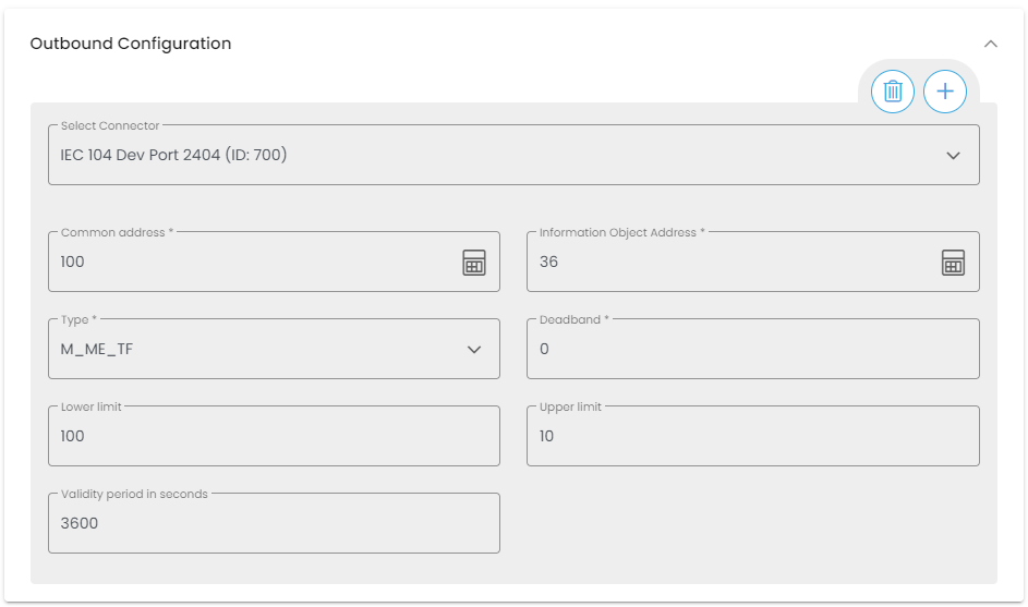
The data points are configured in the UI in the data point of a digital twin or a virtual device (see figure below). For larger data point volumes, the external API (XAPI) can be used for a convenient and scalable import. For preparation, it makes sense to create a mapping table that assigns the data point identifiers used in niotix to an information object address. The individual digital twins are mapped to the general address, for example. The configuration can then be carried out with the help of a special API endpoint by iteration via the digital twins or virtual devices (see XAPI documentation).
In addition to defining the respective IEC connector, the following parameters are defined:
- Common Address (ca): The address is referred to as the common address as it is linked to all objects contained in the ASDU. Assignment of the common address (CA; min: 1, max: 65534).
- Information Object Address (ioa): Each information object is addressed by an information object address (IOA), which identifies the respective data within a specific station. Its length is 3 bytes for IEC 104. The address is used as the destination address in the control direction and as the source address in the monitoring direction. Assignment of the information object address (IOA; min: 1, max: 16777215).
- Data type (type): The standard IEC data type must be selected here. The different data types can be found in the niotix Interoperability Statement.
- Deadband (db): Sets the threshold value for each measured data point. A value change must be greater than the deadband in order to be reported as an event-driven event. The setting is optional (default value = 0.0) and only relevant for measured values. Permitted types are int and float (e.g. “deadband”: 3.0)
- lowerLimit (lower limit value): Optional, required for automatic setting of the quality flags. If the value of the data point falls below the lower limit, the lower limit is set as the value and the data point is given the “Overflow” quality flag. The lower limit value must be less than or equal to the upper limit value. An “Overflow” quality flag is only set for measured values (type 13 or 36).
- upperLimit (upper limit value): Optional, required for automatic setting of the quality flags. If the value of the data point falls below the lower limit value, the lower limit value is set as the value and the data point is assigned the “Overflow” quality flag. The upper limit value must be greater than or equal to the lower limit value. An “Overflow” quality flag is only set for measured values (type 13 or 36).
- validityPeriod (validity period in seconds): Optional, required for automatic setting of the quality flags (must be activated in the configuration of the niotix IEC-104 server by setting the “validity-check-interval-in-s” parameter). If the timestamp of the data point in the IEC server (time of receipt) is older than the validity period, it is given the quality flags “Invalid” and “Not Topical” during the next check after the interval (“validity-check-interval-in-s”) has expired. The “Not Topical” quality flag is not set for the counter values (type 15 or 37).
niotix IEC-104-Server
The niotix IEC-104 server component sends niotix data values via IEC 60870-5-104 to the IEC-104 master (e.g. a network control system).
IEC 60870-5-104 services
The niotix IEC-104 server supports various services that are defined by the IEC 60870-5-104 protocol. These include
- Interrogation Command (C_IC_NA <100>): Interrogation command for data points.
- Counter Interrogation Command (C_CI_NA <101>): Query command for counter data.
- Read Command (C_RD_NA <102>): Read command for data points.
Data transmission and configuration
The measurement data is sent to the niotix IEC-104 server via the webhook connector when a data point is updated in a digital twin or a niotix virtual device. The niotix IEC-104 server performs a dynamic configuration and dynamic addition/removal of IEC-104 servers and data points. The configuration is saved and restored on restart.
Quality flags
Data points can be marked with quality flags that indicate the status of the IEC-104 data points:
Limit values
For measured values with data types 13 (M_ME_NC) and 36 (M_ME_TF), the “Overflow” quality flag is set if the value exceeds the “upperLimit” parameter or falls below the “lowerLimit” parameter. The data point is then set to the value of the upper or lower limit. If the “upperLimit” or “lowerLimit” parameters are not set, this function is inactive for the corresponding data point. This function requires niotix IEC-104-Server version 2.3.1 or higher.
Validity check
For all data types with the exception of 15 (M_IT_NA) and 37 (M_IT_TB), the quality flags “Invalid” and “Not Topical” are set if the timestamp is older than the validity period (validityPeriod). For data types 15 and 37, only the “invalid” quality flag is set.
The frequency of the check is defined in the niotix IEC-104 server via the “validity-check-interval-in-s” parameter (see Configuration section). This function requires niotix IEC-104-Server version 2.3.1 or higher.
Available data types
The niotix IEC-104 server supports four different IEC 60870-5-104 data types, each with or without a timestamp:
| type number | description | short name |
|---|---|---|
| 1 | Single point information | M_SP_NA |
| 3 | Double puncture formation | M_DP_NA |
| 13 | Measured value, short floating point number | M_ME_NC |
| 15 | Count value | M_IT_NA |
| 30 | Single point information with time stamp | M_SP_NA |
| 31 | Double point information with time stamp | M_DP_TB |
| 36 | Measured value, short floating point number with time stamp | M_ME_TF |
| 37 | Count value with timestamp | M_IT_TB |
Event reporting
Event data, or so-called spontaneous data transmission, enables the transmission of data points when values or flags change. Events are only triggered when the value of a data point changes, but not when the timestamp changes. Events for measurement data are only triggered if the deadband has been exceeded.
Configuration
The niotix IEC-104 server offers various parameters for configuration (see docker-compose.yml):
- logging.level.com.digimondo: Setting the log level (TRACE, DEBUG, INFO, WARN, ERROR).
- http-auth-enabled: Activate/deactivate HTTP basic authentication for the health and metrics endpoints.
- http-auth-user: User name for HTTP basic authentication.
- http-auth-pass: Password for HTTP basic authentication.
- buffer-interval-in-ms: Time interval in which data can be buffered (0 for deactivation).
- delete-dp-interval-in-s: Time interval for deleting data points (0 for deactivation).
- config-backup-path: Path to the backup file for the IEC server configuration.
- validity-check-interval-in-s: Length of the interval in seconds at which the age of the data points is checked. Optional, required for automatic setting of the quality flags
- metrics-endpoint: the URL of the metrics endpoint. IEC104Server sends metric data to this endpoint via HTTP POST. See below for a detailed description.
- metrics-post-interval: the interval in seconds for posting metrics to niotix. Setting the interval to zero disables posting of metrics data.
Metrics data
The niotix IEC-104 server provides a metrics object that contains the active data points of all IEC-104 server instances. The metrics object is provided via an API endpoint and can be transferred to a defined endpoint via HTTP POST.
Local API endpoint (curl):
curl --location 'http://<IEC104Server-IP>/metrics/'
Example response:
{
  "data": {
    "servers": [ // List of active IEC-104 server instances
      {
        "id": "123", // ID of the IEC-104 push connector
        "port": 2404, // IEC server port
        "status": "ok", // Status can be "ok" or an error message, e.g. "port already in use by other server"
        "numConnectedClients": 2, //Number of connected IEC 104 clients
        "lastConfigChange": "2020-08-18T13:28:53.000Z", // last configuration change of the data point
        "lastDataUpdate": "2020-08-18T13:28:53.000Z", // last data update
        "dataPoints": [
          {
            "ca": 1,
            "ioa": 146,
            "value": 0,
            "flags": [
              "invalid"
            ],
            "timestamp": "2020-08-18T13:28:53.000Z",
            "type": 36,
            "deadband": 0.0,
            "group": 0
          }
        ]
      }
    ]
  }
}
Installation variants
The niotix IEC-60870-5-104 module offers flexible installation options to meet the requirements of different IT architectures. The following installation variants are available:
“Standard” variant
- niotix as SaaS: niotix remains available to users as a SaaS platform in the cloud.
- IEC 104 Server in the customer’s IT infrastructure as a Docker container: The IEC 104 Server is provided as a Docker container and operated in the customer’s internal IT infrastructure. This fulfils security requirements in particular.
Communication sketch
“OnPremise " variant
- niotix and IEC 104 server in the customer’s infrastructure: Both niotix and the IEC 104 server are deployed internally in the customer’s IT infrastructure, allowing full control and customisation options.
Communication sketch
VPN requirements
Certain requirements for a Site2Site VPN are necessary for smooth integration in the “Standard” variant:
- IKEv2 support
- Port forwarding: Port 500 in + out (UDP)
- Whitelist of compatible software and hardware see Link
System requirements
The following requirements are specified for the “Standard” and “OnPremise” variants:
- CPU : 2 cores
- RAM : 8 GB
- HDD : 50 GB
- OS : Ubuntu 16.4 or higher
- Software: Docker Host and Docker Compose (delivered as Docker image)
- Other: Internal URL as target for receiving data from niotix
Steps for configuration
Creating the connector
The first step is to create and configure a niotix IEC-60870-5-104 Push connector in the respective account. This is done in the menu item Integrations / Connectors. For information on the settings, see above.
Configuration of the data points
The data points are configured in the UI in the data point of a digital twin or a virtual device. For larger data point quantities, the external API (XAPI) can be used for a convenient and scalable import.
Configuration via XAPI
The external API (XAPI) can be used for a convenient and scalable import for larger data point quantities. For preparation purposes, it makes sense to create a mapping table that assigns the data point identifiers used in niotix to an information object address. For example, the individual digital twins are mapped to the general address. The configuration can then be carried out using a special XAPI endpoint by iterating over the digital twins or virtual devices (see Link). In the JSON body of the PUT command, the “outboundConfiguration” array is used with the following fields:
- “connectorId” requires the ID of the niotix IEC-60870-5-104 push connector as the value.
- The “config” object contains the parameters for the data point configuration (see above for explanations).
- ca
- io
- type
- db
- lowerLimit (optional)
- upperLimit (optional)
- validityPeriod (optional)
Example without optional parameters:
{
  "outboundConfiguration":[
    {
      "connectorId":123,
      "config":{
        "ca":256,
        "ioa":65537,
        "type":13,
        "db":0
      }
    }
  ]
}
Configuration via UI
If the connector is activated, the new “Outbound configuration” field appears in all data points of the digital twins and virtual devices. If the connector is selected here, it is possible to enter the IEC 104 addresses in decimal or structured form.
Creating an integration flow
To send the data points to the server, an integration flow must be created. To do this, a filter and a transformation must be created and integrated into an integration flow in the following sequence:
- filter
- transformation
- connector
Creating the filter
The filter ensures that only messages from data points for which the object outbound_values exists are sent to the IEC-104 server. Example configuration:
- Mode:
extended - Type:
JSONATA - Code:
$exists(meta.outbound_values)
Creating the transformation
To create a complete integration flow, a transformation must also be created.
Only the output type must be changed to application/json. The input remains unchanged for the transformation itself.
- Output type:
application/json. - Code:
$