The function of the virtual devices is to integrate different data sources of the Internet of Things into niotix. It is not relevant which transmission technology is used as virtual devices are technology-agnostic.
Data flow from the physical sensor to a virtual device
The central input point for sensor data in niotix is the connectors (). They offer the option of receiving data via various protocols and transforming it to the required input format.
Devicedrivers( ) parse the incoming payload as required and assign the data to target variables.
Based on a connector and a device driver, virtual devices ( ) can be created on which the data can be (historically) viewed. If many similar virtual devices are to be created, the use of a device template () is recommended to ensure maximum consistency and simpler administration.
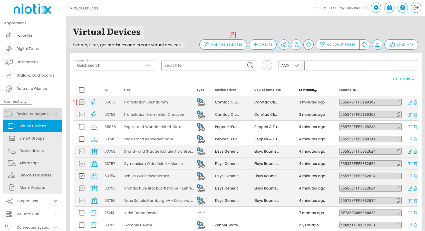
Virtual device overview
In this overview, it is also possible to create new virtual devices, show the favorites view or display the virtual devices on a map.
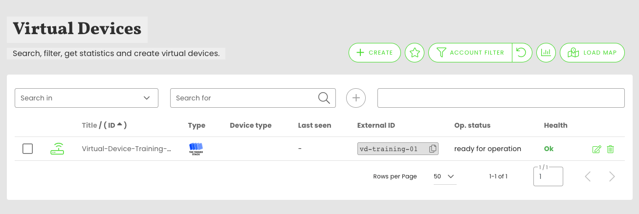
In addition, the virtual devices can be edited from this overview by pressing the corresponding pencil button on the right of the table. If necessary, virtual devices can also be deleted.
In this view, the same filters can be applied to limit the selection and adapt it to needs.
By default, filters work on “partial hits”, i.e. a filter for Id 123 finds both the device with the Id 123 and all other devices with this character combination, e.g. 1123 or 51234. To get only “exact hits”, the filter criterion must be set to " “, e.g. “123”.
Meaning of special table columns:
- “Last seen”: This value indicates how much time has passed since the arrival of the last data packet.
- “External ID”: virtual devices can have different data sources. They represent objects from the connected data sources. This value specifies the ID of the object in the connected data source.
- “Health”: this value expresses whether everything is OK with the virtual device. If a warning or an alarm is displayed, the value can be clicked to ignore the alarm or the warning. Furthermore, several warnings and alarms can exist for each object, these are displayed after clicking. Ignored warnings or alarms can be set to active again when editing the object.
Create virtual devices
To easily and quickly create a new application, click on the “Create” button () . A new window opens where the user first selects an account to which the virtual device should be created. After selecting the account, the second field to the right of it shows the connectors available for the account. Use the option “Create virtual device build on template” to use a template instead of a connector.

Once a connector/template has been selected, both fields are locked for editing and can be subsequently adjusted again using the change button. In the next step, a new virtual device can be created for this connector or an existing virtual device can be imported. If the user decides to import an existing virtual device, he enters the external identifier of the device in the corresponding input field and presses the “Import” button. After that, the virtual device is searched in the system connected by the connector. If the search is successful, all possible input fields are pre-filled. If it is determined during the import that the device is already recorded in the system, a corresponding message is displayed to the user and then the user can decide whether he wants to continue using the already created device or still import the device a second time.
By clicking the “Create” button () , the user can create a new virtual device. The input fields to be filled in in order to create a new device will appear:
- Title:* Give the device a meaningful title for easy identification.
- Parent object:* In this input field, you can select the digital twin to whose authorization environment the virtual device should be created.
- Description: Enter a short description of the device that will appear on the detail page. (Supports Markdown formatting)
- Tags: Use a dropdown to select tags that already exist in the system or to enter new tags.
- Operational status: You can choose between “Not set”, “On the way”, “Operational”, “In operation”, “Temporarily inactive” or “Shut down”. To check the status for the report display on the details page, the most recent operating status of the device is combined with the threshold value.
- Devicedriver: If the virtual device belongs to a specific devicedriver, you can select this type from the list and assign the devices directly to interpret the payload of data packets during installation and after commissioning.
- Groups: Virtual devices can be assigned to an infinite number of device groups. In the dropdown “Groups” you can choose between the different groups already existing in the system. You can also select multiple groups. If the corresponding device group does not exist in the system, a new device group can be entered in the “New device group” input field and added to the existing groups by clicking the button with the plus symbol.
Edit virtual devices
Virtual devices already registered in the system can be viewed and edited by the user. Edit a single device by clicking on a device in the overview list or on the “Edit” icon on the right. This will take you to the device information.
Here you can change various properties like title, EUI, description, and other fields. In this tab, the type of the device is displayed in the upper left corner, which is used to interpret the payload, among other things. This devicedriver is clickable and leads the user after clicking directly to the overview of the corresponding devicedriver. To the right of the devicedriver, the user is shown when the device was created and how much time has passed since the last incoming data packet. To the right of this information is a dropdown for selecting a relative or absolute time period. This time period specifies for which time period all the information listed below will be prepared.
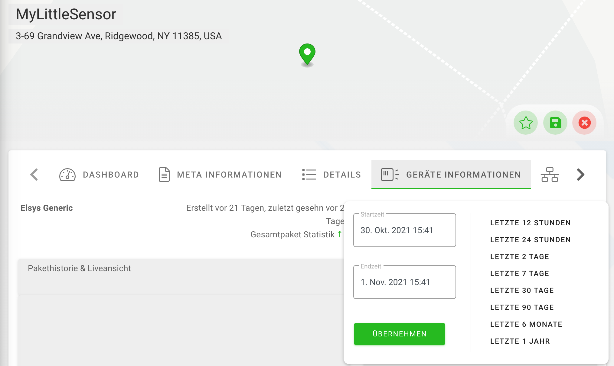
In the next line, the user will find the packet history as well as the live view. Here, all packets are listed that were received by the system in the selected time period. If the selected period ends in the current time, packets received in real-time are displayed live in the packet history. To the right of the packet history is the packet visualization. In the packet visualization, on the one hand, the raw received data of the data packet is displayed in JSON format, moreover, the payload interpreted by the previously assigned devicedriver is displayed as JSON.
In the next section, the user is shown a bar chart visualizing the packet volumes received by the system in the selected time period. Here, the colored bars show the currently selected time period, and the gray bars show the previous time period. This gives the possibility to easily see if the device is sending data reliably compared to the previous period.
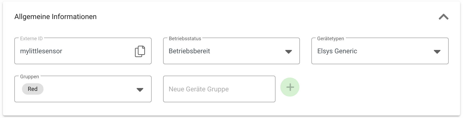
Below this, there is now the general device information such as external, e.g. identification number, the operating status, the devicedriver, and the device group(s) as well as the possibility to add a new device group. All data can be changed and saved here.
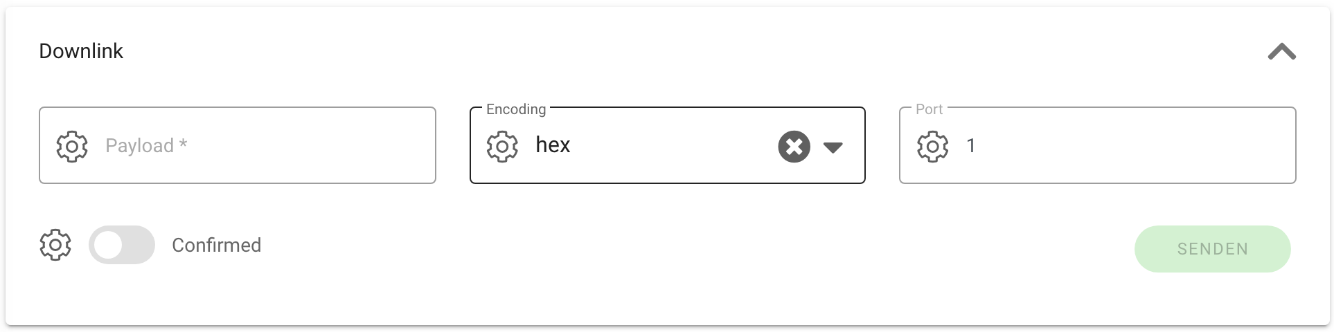
Below this, the user will find the section of downlinks. Here you can enter a payload, select encoding, and a corresponding port over which the payload is to be sent. In addition, it is possible to select whether the downlink should be confirmed by the system or not. By clicking on the “Send” button, the corresponding downlink is sent to the virtual device in the real world.
Edit & Delete Multiple Devices
Edit and delete up to 500 devices by selecting the desired virtual devices via checkboxes in the overview list and then clicking the “Manage selected” button. Alternatively, you can select the desired virtual devices using filters. In this case, all virtual devices matching the currently applied filter criteria will be affected.
A dialog will open, guiding you step by step through the configuration of the desired changes.
1. Select Mode
Choose the desired mode from the dropdown. The following options are available:
- Edit meta information: Allows you to make the following changes:
- Delete all selected virtual devices
- Link virtual devices to a template
2. Configure Changes
The available options depend on the selected mode.
Available options in the “Edit meta information” mode:
- Change operational status
- Change parental object
- Add group: Add one or more groups to the selected virtual devices. The groups must already exist.
- Remove group: Remove one or more groups from the selected virtual devices. Groups that were assigned via a device template cannot be removed.
- Add tags: Add one or more tags to the selected virtual devices. The tags must already exist.
- Remove tags: Remove one or more tags from the selected virtual devices. Tags that were assigned via a device template cannot be removed.
Available options in the “Delete all selected virtual devices” mode:
- Do not remove from remote system: The virtual devices are only deleted in niotix. They remain in connected systems, such as the Firefly network server.
- Delete from remote system: The virtual devices are also removed from connected systems, such as the Firefly network server.
Available options in the “Link virtual devices to a device template” mode:
You can select applicable device templates. Only templates that use the same account, connector, and device driver as the selected virtual devices will be listed.
3. Apply Changes
In the final step, you can add a title to the changes to help track them later.
After clicking “Apply changes”, a background job will be created. This allows you to continue using niotix while the changes are being processed.
You can monitor the progress of the background jobs under “Background jobs”.
Change devicedriver
The last section of this overview contains the connector-specific data. This data cannot be changed and is read at runtime from the system that is connected by the connector and displayed. If there is a wish to change this data, the user must log in to the connected system and perform the data change there.
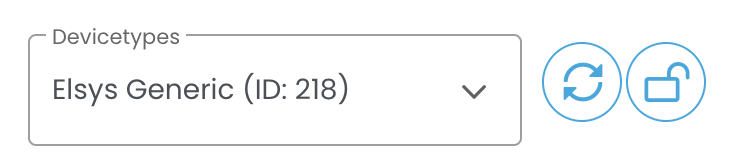
There is both the option to resynchronise a devicedriver to apply changes of a devicedriver to the virtual device, and the option to change the entire devicedriver.
Both functionalities should be used with caution, as that change to the Virtual Devices will also affect data states in Digital Twins and these may need to be re-created to receive data again. The data in the Virtual Device itself will be deleted with both functionalities.
To resynchronise the devicedriver of a virtual device and apply the changes of the devicedriver to the virtual device, click on the button next to the devicedriver and then save the virtual device.

To assign a new devicedriver to the virtual device, the list of available devicedrivers must first be unlocked. To do this, click on the button with the lock. The desired devicedriver can then be searched for and selected. Once the correct devicedriver has been selected, save the virtual device.

Please note that the changes to the virtual device are only applied when the device is saved.
Important Data States
Each of these objects has three non-erasable data states which are generated automatically. The “_raw” data state is the unmodified data that is sent to the object. The “_parsed” data state contains the JSON generated from the raw payload of the sensor after passing through the parser in the devicedriver. The “Health” data state stores the information for determining the “Health”.
The “_raw” Data State.
This data state contains the unchanged data received at the connector for this device. Since only the payload for the calculation of the individual measured value data points is used for further processing, this data state is used to derive specific data points, e.g. for RSSI/SNR/SF in LoRaWAN cases. In addition, the state enables a reliable revision of the data.
The “_parsed” Data State
This data state contains the JSON generated by parsing the raw payload. It can be used, for example, to create aggregated data states that contain calculations from different measurements. In addition, it is suitable for forwarding data to third-party systems if more than one measurement point is to be further processed.
“Health” Data State
The data state is particularly important because the calculation for the system status of the object takes place in it. In edit mode, you can select from all data states created by the devicedriver that are relevant for determining the “Health”. After that, when a specific detection logic is defined for each selected item. Program examples are given for this determination logic.
For example, a device can receive a warning when the battery level is below 40% and an alarm when the battery level is below 20%. At the same time, another alarm can be triggered if the device reports an error. The “Health” can therefore assume and display several faulty states at the same time.
To avoid having to configure every device, the configuration can be prepared once in the devicedriver. This can be done under “Device Health Config” and applies to all devices created afterwards that are assigned this devicedriver.
Overview of different health states and evaluation logic
The health state will be evaluated with every new packet that is processed for the device and additionally in a time interval defined by the health check - rule which is created automatically with the health state. By default this rule is executed once a day, so that even if not data is arriving to the sensor an alarm will be created for this devices if for example the health state is configured to set an alarm if no data was received for example for 24 hours.
Different health states:
- Unknown: before a device receives the first data packet the health state status will always be unknown, even though there might be configuration to check for packets every 24 hours. This is to more easy distinguish devices which have real errors from those which are not activated yet but were already imported to the system.
- Ok: If devices received at least on data packet in the past and have no warnings or errors.
- Warning: If according to the configuration of the health state an error is detected.
- Alarm: If according to the configuration of the health state an alarms is detected.
- Invalid: If there is no health state for this device (could be devices which were created before the health state was available) or the value can not be interpreted by the system (which might occur if the health state has a custom javascript transformer). You can not filter for this status due to technical reasons.
Authorisations
All virtual devices, unless otherwise set, are created to the root twin of the corresponding account when the device is created or when the device is changed. This means that only users who have permission to view and/or change the root twin can see the devices. If a device is to be given a different permission setting, for example to belong to the permission group of a child twin, this can be set by changing the parent object (under Meta information).
For a user to have viewing as well as writing permissions of the virtual devices, the following roles are required on the respective account: DigitalTwin.list and VirtualDevice.manage.
For a user with only reading rights to the virtual devices, the VirtualDevice.read role is required.
Devicedriver
Under the menu item “Devicedriver” you will see a list of the devicedrivers to which you have access with your account. Here you create templates for using and grouping devices with the same functions and data structures with the appropriate user rights. You can use standards for converting packet data via a packet parser. A detailed information can be found here Devicedriver